Decoding with dl-fldigi
Before following this section, make sure that you can receive the UHF radio transmissions, using either a "real radio or an SDR (Software Defined Radio);
- Suitable real radios include the Yaesu 817, Icom IC-R10, Icom IC-R20, AOR AR8200, Yupiteru MVT-7200. The radio or scanner needs to be able to receive SSB transmissions in the 434MHz (70cm) band. With the PITS software running, you should be able to hear the transmitted data from the radio speaker, by setting SSB mode and tuning in to about 434.450MHz (default in the PITS software). Once you can hear the signal, you can proceed with connecting the radio to your PC using a 3.5mm audio jack cable, and then decoding the data.
- Suitable SDRs include various TV dongles (see http://ukhas.org.uk/guides:sdr_tracker), the Funcube Dongle, and the AirSpy unit. You get what you pay for here, and whilst the cheap TV dongles do work, the other devices are much more sensitive and will work over greater distances. The SDR software (there are several choices including SDRSharp and HDSDR) can send the resulting audio signal to a "virtual" audio cable, provided by software which you need to install (see http://en.wikipedia.org/wiki/Virtual_Audio_Cable).
The Pi In The Sky software transmits data using 2 slightly different radio fequencies, which are converted by a radio receiver (SDR or a "real" radio) to 2 audio frequencies. These 2 tones have to be converted to digital 1's and 0's - a process is called "demodulation - and this is done by a free program called dl-fldigi, which is a modified version of fldigi.
The "dl" part of the name stands for "Distributed Listener". The "dl" modifications upload the demodulated data to web servers which collate information from all listeners of your payload. By using this system, you are "crowd sourcing" the reception of your balloon telemetry and live images, meaning that even if you fail to receive part of the flight, hopefully someone else will be able to fill in the gaps. Of course this only happens if you publicise your flight!
So, download and install dl-fldigi from here. For more information about using dl-flldigi see here.
When you first start dl-fldigi, you will be asked to enter your callsign (which could be a Ham radio callsign, or some suitable identifier (e.g. school name)). It's best to use something fairly short (say max of 8 characters) as the callsign will later appear on the live map.
The most important setting is the audio source - i.e. the device that it will listen to for those 2 tones. If you are using a real radio then that is connected to the "line in" socket (or "mic" if you don't have one) so you should select "Line In". For an SDR you need to select the device that you set that up for - e.g. "Stereo Mix" or "Virtual Line 1" (see http://ukhas.org.uk/guides:sdr_tracker for more information).
Once the initial setup process has finished, you need to set the parameters of the signal from your tracker. To do this, first select RTTY by choosing "Op Mode" then "RTTY" then "Custom" from the menu:
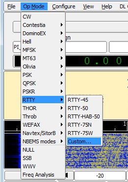
Then set the following:
- Carrier Shift: (Custom) 600Hz (910Hz for earlier boards)
- Baud Rate: 300 baud
- Data Bits: 8
- Parity: None
- Stop Bits: 2
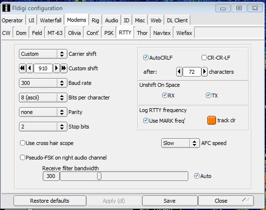
Click on Save and then Close.
Now tune in your radio to the signal. Make sure that the radio or SDR software is set to USB mode.
If it's a real radio, make sure that if you turn the frequency knob down (to a slightly lower frequency) then the audio tones you here go *up* in frequency. If not, you are tuned to the "wrong" side of the signal and you need moving the frequency knob further down until the audio tone disappears and then comes back again - this time the tones will get higher in pitch as you tune downwards. Now connect the radio audio output to your PC line input with a 3.5mm jack cable.
Now look at the waterfall at the bottom of the dl-fldigi window. You should see the 2 tones as 2 vertical bands (see below):
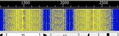
Click on the waterfall, midway between those 2 bands. Now you should see 2 red cursor lines one in the centre of each of those bands, and 2 red filter bands above
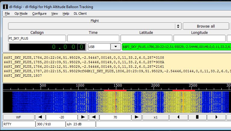 :
:
And once that's done, you should see data appear in the text window above. I suggest you do this with the camera disconnected or disabled, so you only have text in that window, which makes it easy to see if it's working or not. You can see above that the text window has telemetry from the tracker - GPS location etc.
If you do send images, you don't have to do any more setup - dl-fldigi will decode the image data automatically. You can view those images using the menu option View --> SSDV.
Published on