Making A LoRa Tracker
To build a LoRa gateway you need:
- Pi In The Sky tracker board
- Pi In The Sky LoRa board
- Raspberry Pi A+ (but easier to use one with LAN for testing)
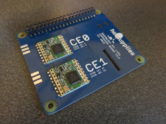
LoRa Board
This one is populated with 2 LoRa modules, however please note the following limitation: The first LoRa position (CE0) is not compatible with earlier Pi In The Sky tracker boards (because those boards used an SPI A/D converter. To use this second position you need V2.5 or later of the Pi In The Sky tracker board (which has an I2C A/D converter instead).
Software
Follow the usual instructions to set up the SD card with the PITS software
Configuration
There are some addition settings which relate to LoRa. See the main confiiguration page for how to edit the settings file, and what the other settings are. The only settings that are needed (and the only ones we have documented) are these:
LORA_Frequency_0=434.400
LORA_Payload_0=PI_SKY_TEST
LORA_Mode_0=1
"_0" refers to the module in the CE0 position; "_1" would refer to the module in CE1 position. Be sure to edit the relevant lines.
LORA_Frequency_0 sets the frequency in MHz. Take care to use a frequency that is legal to transmit on (e.g. in the UK make sure you comply with IR2030).
LORA_Payload_0 sets the payload ID, which should be unique (to avoid conflicts with other balloons). In particular it should not be the same as that used for RTTY or the other LoRa channel if both are in use.
LORA_Mode_0 sets the "mode" of transmissions. We recommend mode 0 for just telemetry, or mode 1 if you also wish to transmit images.
Published on